|
|
|
|
  
Demonstration no.: 6 Description: Drill a long row of small holes in a metal tube. 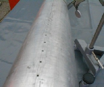
Metal tube with long row of drilled holes.
The tube is closed in one end by a rubber membrane and in the other end by a plug through which gas can be let into the tube. A gas cylinder is connected to tube. As the gas flow is turned on, the gas will flow into the tube and out through the small holes. With a lighter or a match, the gas is ignited, and a long row of small flames is formed. A loudspeaker is connected to a frequency generator, and a pure sound wave is directed towards the rubber membrane. The sound will enter the tube, and if the frequency is right, a standing wave is formed. This standing wave can be seen directly as differences in the height of the individual flames. 
Diagram of the Ruben flame tube.
It can be quite difficult to create a good standing wave, so the flames form a clear pattern. Try changing the gas pressure, sound intensity and sound frequency. The demonstration should also be done where the frequency generator is replaced by a CD- or MP3-player (plus amplifier). This allows you to send music into the tube, making it possible to see the flames dance in tune to the drums and base. 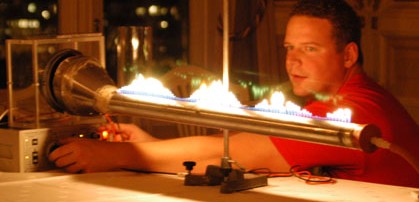
Picture of the Ruben flame tube in use.
In the above picture, the rubber membrane is made out of an ordinary balloon. There is also a funnel channelling the sound from the loudspeaker to the membrane. In the picture below, the membrane is made of a rubber glove. This tube has a larger diameter, and the funnel is not needed to make this tube work: 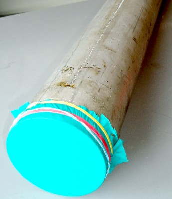
Picture of the Ruben flame tube.
In many descriptions of this experiment in the litterature, the loudspeaker is placed on the tube itself with some gastight seal (e.g. plastic and tape). 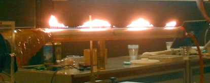
Picture of the Ruben flame tube in use.
In the references listed below, the flame tube has been constructed using different designs. Here are examples of dimensions used in flame tube construction:
The Ruben flame tube is named after H. Ruben, who published the demonstration experiment in Annalen der Physik in 1905 (right after Einstein's famous 1905-article on the photoelectric effect!). In 1975, an American physics teacher presented a flame tube built out of a linear air track. He remarked that the flame tube experiment is only rarely performed in schools due to the requirement of very specialized equipment. In reality, all you need is some tube with a long row of small holes, exactly as you find in a standard air track. All rows of holes - but one - can for instance be covered with tape. One might think that where the standing wave has a node, the flames will be small. Unfortunately, the physics of this experiment is not quite that simple. As discussed in the references below, it is actually possible to achieve two different modes of operation by varying the gas and sound pressure! For a given sound intensity, the flames will typically be highest at the anti-node of the standing wave (i.e. the pressure node). If the gas pressure is reduced, the flames at the nodes will be the highest. For a given gas pressure, a high sound volumen results in high flames at the nodes and the reverse at low sound volumes. Ficken and Stephenson show in their article that the gas flow out of a hole can be written as: 
Relation between gas flow, gas pressure and sound pressure for a given sound frequency omega.
So, for low gas pressures and large sound pressures, atmospheric air can actually be sucked into the tube.
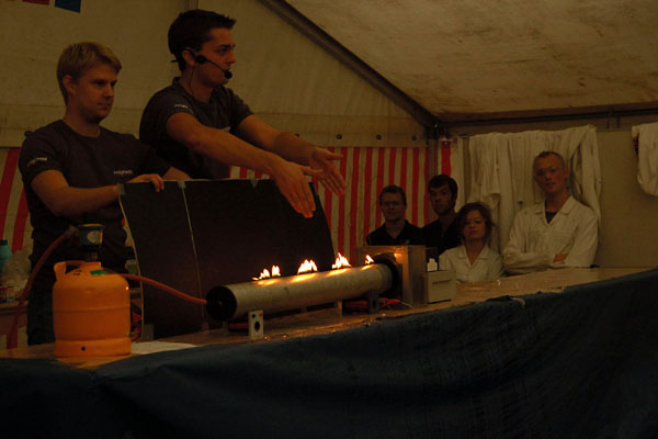
Flammerøret demonstreres på en scene af Fysikshowet under Århus Festuge.
Questions and Answers: What do I do, if the membrane melts? You are propably using a tube of a material, which conducts heat too well. Copper is a bad chioce, because it conducts heat very well. The coefficient of heat conduction of aluminium is only 60 percent of copper, and thus better. Iron is only 20 percent of copper, and thus much better. Finally, the coefficient of heat conduction of stainless steel is only a few percent of that of copper. Stainless steel, however, is a very hard metal, making it much more difficult to drill the holes. Also, make sure that the hole are not located too close to the rubber membrane. Why does the demonstration not work? It can be difficult to find the right settings. Try changing the gas pressure and sound frequency. Possibly, you should improve the location of the loudspeaker compared to the rubber membrane. Try also to make a funnel that can channel the sound to the membrane, or try to increase the sound volume very much. Is their a risk of creating an explosive mixture of gas in the tube? No, luckily not. Explosive gas is for instance a mixture of hydrogen and oxygen. Hydrogen is far more explosive than butane and propane, which is typically used for gas burners. Equipment and materials:
References:
PIRA DCS: 3D30.50 (Oscillations and waves: Instruments) Updated: 22 September 2008 If you have comments, corrections or suggestions regarding this demonstration, |
 The Ruben Flame Tube
 Gas burner
| FYSIKBASEN.DK was updated on Sunday, 16 June 2008, at 23:01. |